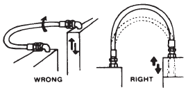
Systems should be designed/engineered to allow for changes in length due to machine motion, vibration, pressures, temperatures, and basic tolerances. A hose assembly must be able to fluctuate its length during service, it should not be taut or unable to grow/expand.
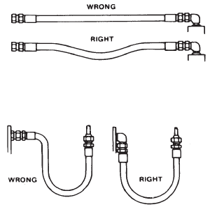
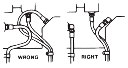
Systems should be designed/engineered to prevent unnecessarily long hose lengths or crossing of lines.
Systems should be designed/engineered to allow for hose movement from changes in pressure or temperature. Use tube supports and do not allow the cover of the hose to rub against sharp objects.
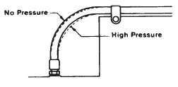
Systems should be designed/engineered to allow for reasonable lengths that are not too short and exceed the minimum bend radius.
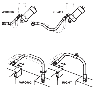
Systems should be designed/engineered to allow hose assemblies to bend on one plane only and prevent hose from twisting. A 7% twist in a permanent installation can reduce hose life up to 90%.
SAE J2593 “Information Report for the Installation of Fluid Conductors and Connectors” covers a range of important tips and instructions on how to safely and properly thread various fittings together including tightening sequences, torque ratings, proper wrench usage, hydraulic system cleanliness, as well as care and maintenance practices. The complete standard can be ordered on-line at www.sae.org or contact our sales staff for further information. Information on SAE J1237 “Recommended Practices for Hydraulic Hose Assemblies” is also available.
Overall Length
When assembling a hose, it is important to note when the “overall length” (OAL) is critical. In most industrial applications (such as water or general purpose) the OAL is not critical, but in many hydraulic applications the OAL can be critical due to space restrictions. The OAL of a hose assembly can be determined by measuring a hose assembly from end-to-end. The following illustrates how to correctly measure specific end configurations (hose should NOT be taut when installed):
- Male threaded ends are measured from the end of their threads (refer to figure AC.1)
- Female threaded ends and Flanged ends are measured from their sealing surface (refer to figure AC.2 & AC.3)
- Angled ends are measured from the center of their sealing surface (refer to figure AC.3 & AC.4)